Boat Fuel System Diagram
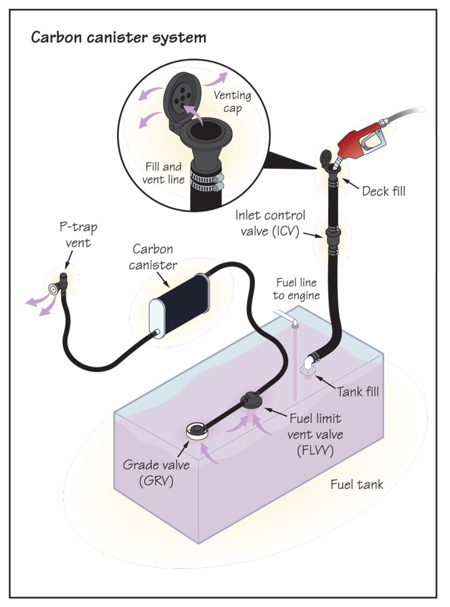
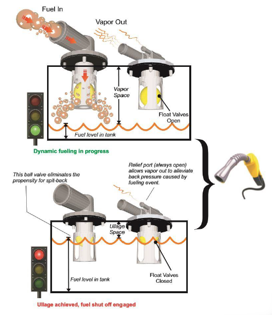
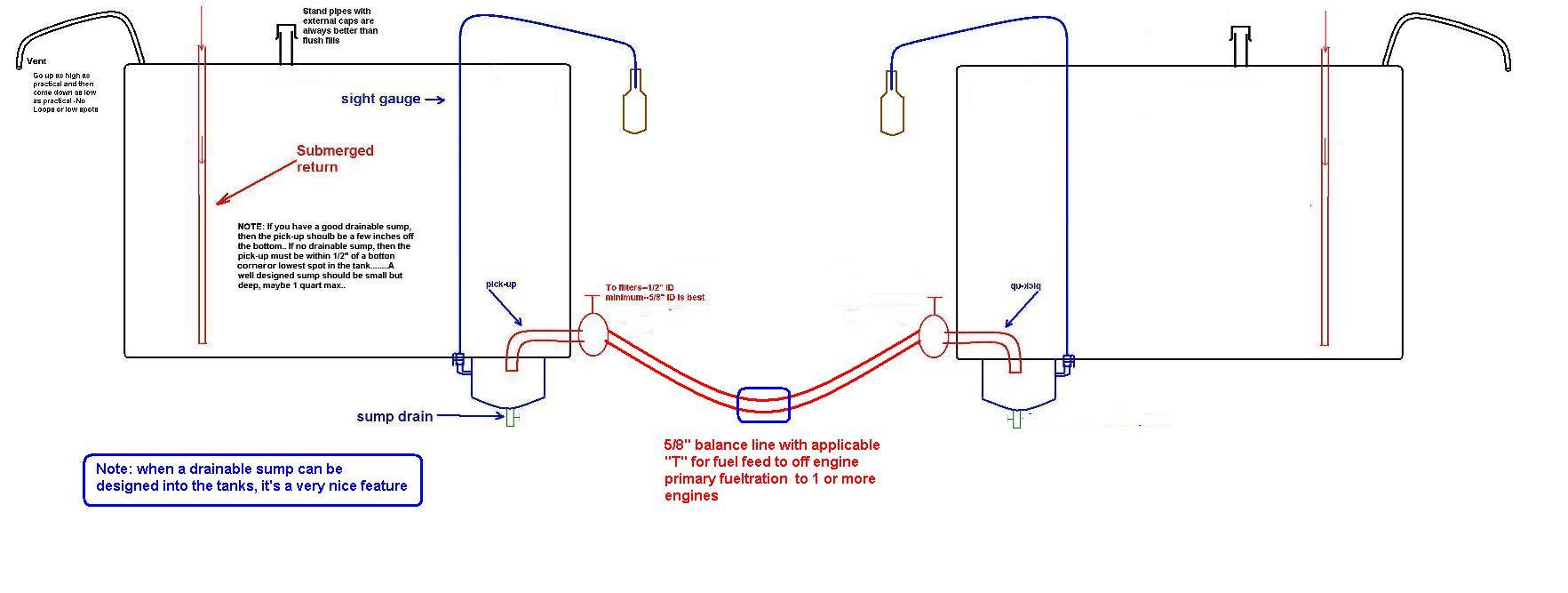
Boat fuel system diagram. To test senders the resistance values are shown at minimum and full gauge scales. Which does not include foam or fiberglass. When both tanks are full the FLVV float in the right tank closes preventing fuel from entering the vent system.
How to install a moeller fuel gauge. This means that evaporating fuel can reach an explosive mixture with the surrounding air inside an enclosed space. Saved by michael appiah.
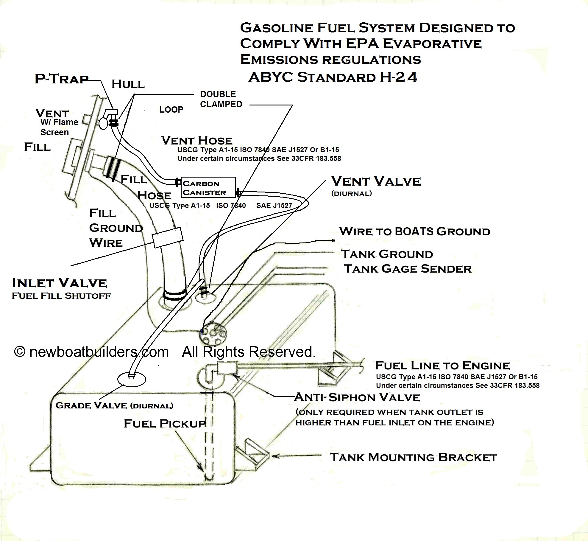
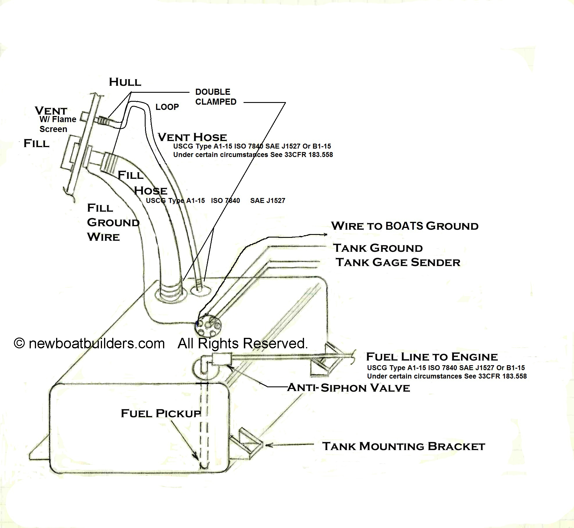
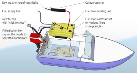
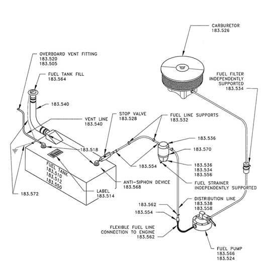
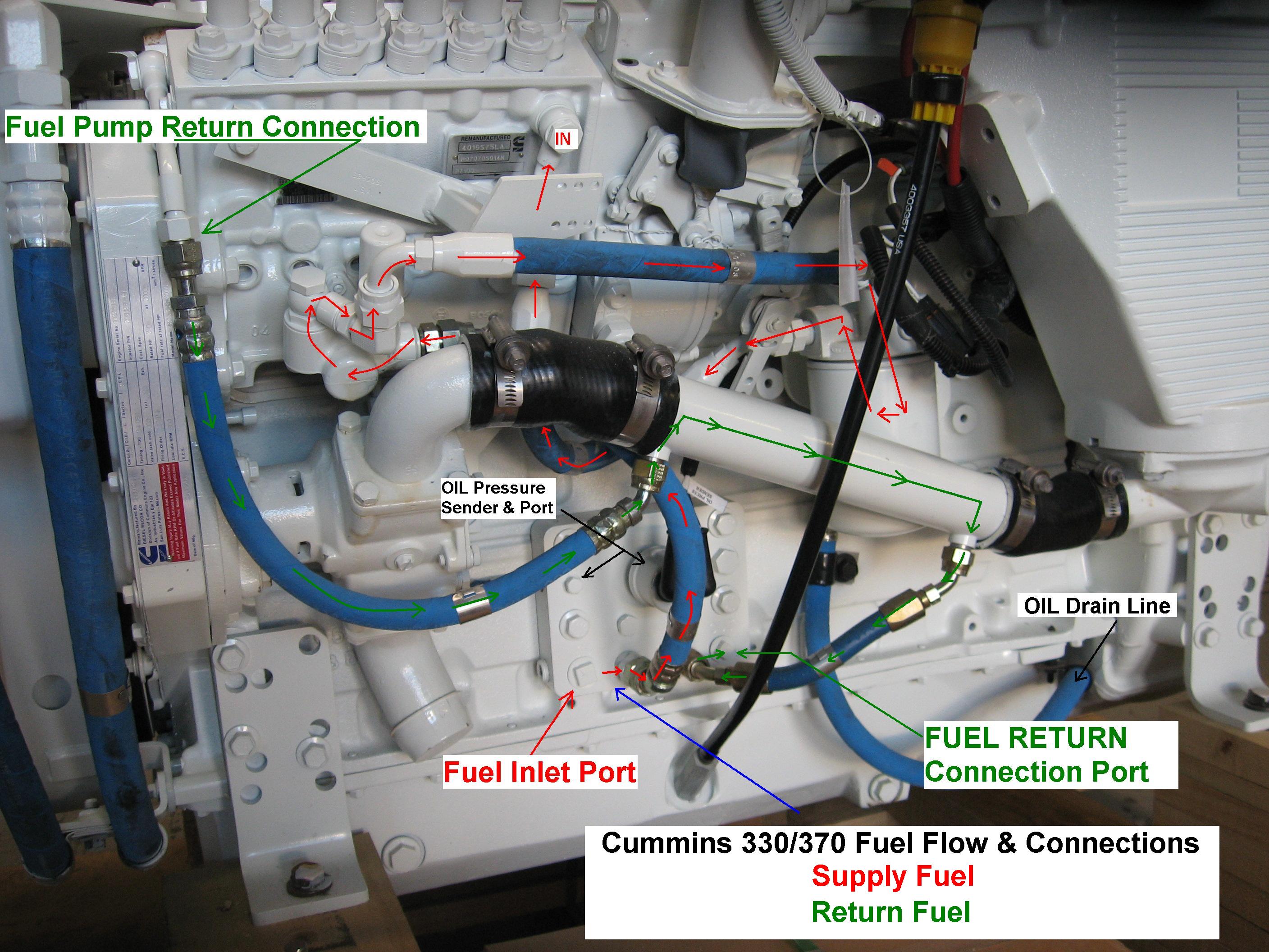
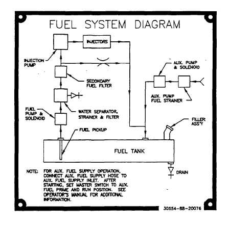
Wide array of boat fuel system diagram wiring representation. Refer to the diagram on the product page for. The sketch in figure 1 provides an overview of the basic requirements for a safe fuel system.
A wiring diagram usually gives information very nearly the relative incline and deal of devices. Most manufacturers recommend a 10. Boat Fuel System Diagram fuelcell energy aktie fuelcell aktie fuellmich fuelcell energy fuel cell füllung für gans fuellmich klage fuelcell energy forum fuelcell energy nachrichten fuelcell finanznachrichten.
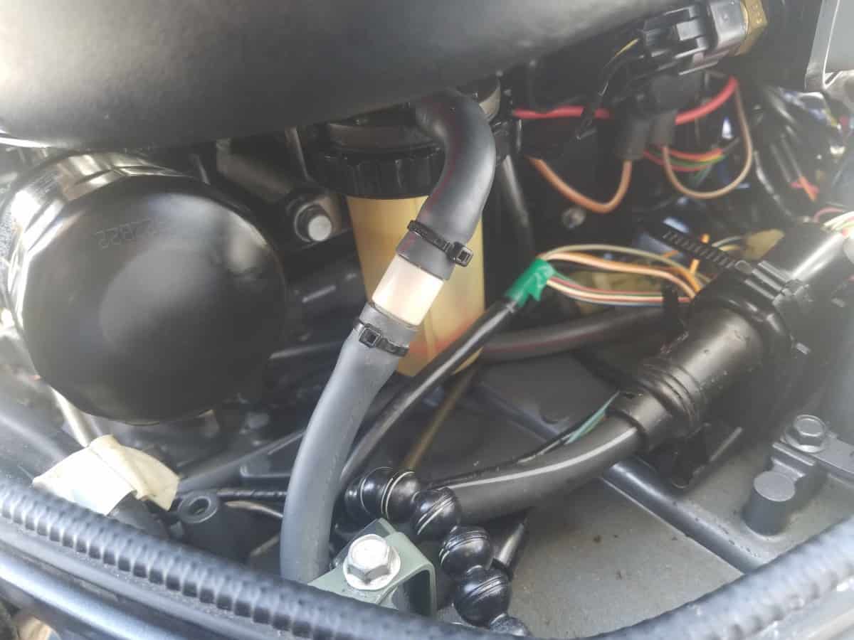
Install the new gauge reconnect the wiring and turn on the power. Boating Magazine What Size Fuel Water Separator Do I Need. Systems on your boat.
Service Manuals 1986-1993 30L 82L Carbureted and Fuel Injected MEFI 1-2 Engines 1993-1998 57L 82L Electronic Fuel Injection MEFI 1-2 1998-2001 57L 82L Electronic Fuel Injection MEFI 3 2001-2007 43L Torque Specs 50L 57L Electronic Fuel Injection MEFI 4 60L Service-Manual MEFI 4 81L Electronic Fuel Injection MEFI 4 MEFI 4 Tachometer. Read or Downloads. It shows the components of the circuit as simplified shapes and the power and signal links surrounded by the devices.
As fuel occupies the interconnected tanks air is forced to vent from the tanks through the FLVV in the right tank. Boat Fuel System Accessories.
Fuel systems marine voltage i to g terminal 10 to 16 volts.
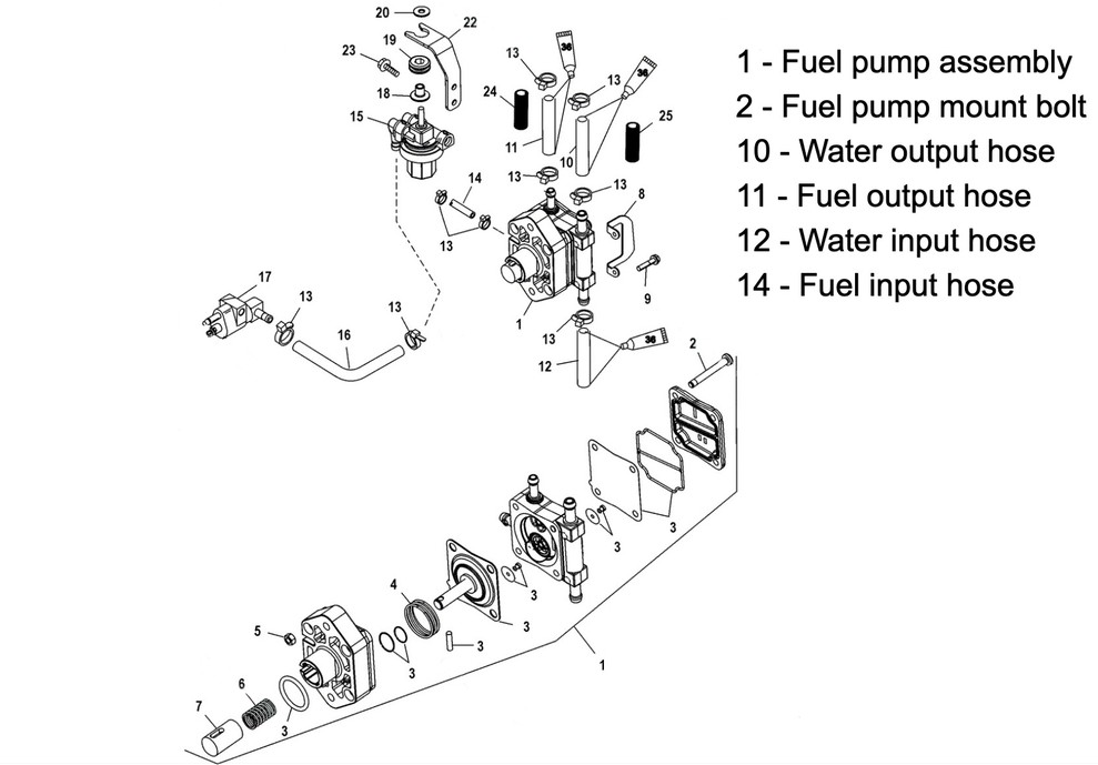
And do not cover diesel fuel systems The following FAQs are written specifically for boat builders and do not cover the requirements for marine engines evaporative emission component manufacturers or a boat builder who chooses to certify their own emission related components. This also causes fuel to back up in the fill hose causing the gas pump nozzle to shut off. Boat Fuel System Diagram fuelcell energy aktie fuelcell aktie fuellmich fuelcell energy fuel cell füllung für gans fuellmich klage fuelcell energy forum fuelcell energy nachrichten fuelcell finanznachrichten. Refer to the diagram on the product page for. Listed below is a photo gallery concerning boat fuel system diagram complete with the summary of the photo satisfy find the image you require. C The fuel system is filled to the capacity market on the tank label. PORTABLE FUEL TANKS are manufactured from a sturdy high-density polyethylene with UV-stabilized resin. Mounting Configuration External In Tank. The Fuel Systems section of this website may be purchased and downloaded.
There are 3 selection valves made alsotank 3 Each engine would get one valve. When both tanks are full the FLVV float in the right tank closes preventing fuel from entering the vent system. It is in PDF format and payment is through PAYPAL Go to the store here 999 USD. Boat fuel system diagram is actually amongst the images our team found on the net coming from reputable resources. Fuel tank usually made of aluminum fiberglass or plastic Hold-down straps to secure the tank 1 ½ deck fill fitting including the gas cap 1 ½ fuel fill hose from the deck fill fitting to the fuel tank Thru-hull vent fitting allows fuel vapors to vent to outside of the boat. The Fuel Systems section of this website may be purchased and downloaded. Boat Fuel System Accessories.











Post a Comment for "Boat Fuel System Diagram"